Tag: The Innovation Platform Issue 17

  • Scalable technology and equipment for direct lithium extraction

    Scalable technology and equipment for direct lithium extraction

    [ad_1]

    With more than 40 years of large-scale industrial adsorption and ion exchange experience, ARi provides scalable technology and equipment for the direct lithium extraction industry.

    ARi has been providing customers with adsorption and ion exchange technology on a large industrial scale for more than 40 years. With our deep knowledge of the operations involved, we fully understand the critical challenges for commercialising direct lithium extraction (DLE) technology on an industrial scale.

    Important issues that need to be considered during commercialisation include:

    • The adsorbent (including its capacity, cost, longevity and the impact of these factors on the operating cost of the plant);
    • The process technology to be used;
    • The equipment to be installed (including the reliable scale-up of this equipment to large industrial sizes); and
    • The impact of the performance of the DLE operation on the performance and economics of the downstream processing steps.

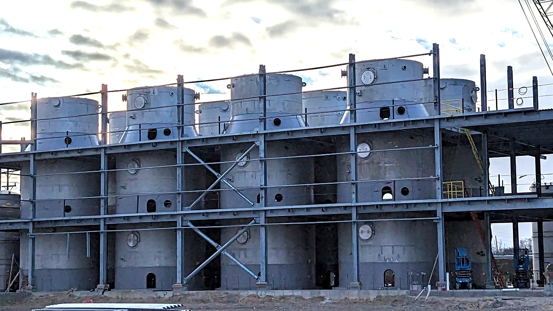
    Due to the relatively low lithium concentration in the brines to be processed, most DLE operations must be carried out at very high brine throughputs. Construction of the largest possible adsorption vessels will, therefore, be critical to minimising the capital cost of the process.

    ARi’s unique experience in the direct lithium extraction industry

    ARi is in a relatively unique position in the DLE industry – having an extensive track record of providing adsorption and ion exchange equipment on the industrial scale appropriate for direct lithium extraction operations while also offering proprietary fractal fluid distribution technology that allows for the simple and reliable scale-up of adsorption operations from pilot-scale testing to full commercial-scale operation at very low risk.

    Since the 1980s, ARi has been providing adsorption, ion exchange and chromatography systems to industrial customers on a very large scale. Typical examples would include the production of high fructose corn syrup production for beverage use or beet molasses desugarisation in the sugar industry, where ARi is undoubtedly the world’s leading technology and equipment supplier.

    In collaboration with their engineering licensee in these markets, Escon GmbH, ARi has provided more than 25 systems in the beet sugar industry alone, employing resin columns with diameters greater than 6.7m (or 22 ft) and total installed resin volumes of the order of 1,000m3 (35,000 ft3) or greater.

    This scale is of the same order of magnitude as is expected to be typical for DLE. Outside of the sugar and sweetener industries, commercial ion exchange, adsorption or chromatography installations of this size are relatively rare, with very few other technology and equipment suppliers having any track record of successful installations.

    Tailored solutions

    As well as being an industry-leading provider of technology and equipment in a range of markets, including DLE and lithium polishing, ARi works with customers to develop innovative processes to meet their specific separation challenges. This service can include the characterisation and selection of resins or adsorbents at a laboratory scale, optimisation and performance testing of the separation process at the pilot scale, and scale-up to a commercial-scale installation.

    Based on expertise gained through decades of experience with resin-based and adsorbent-based separations, ARi can provide customers with a comprehensive overview of their target separation, its sensitivity to changes in operating parameters and its impact on downstream processing operations. This lets customers comprehensively optimise their process economics and performance.

    direct lithium extraction, fluid distributors

    In addition, ARi’s unique fractal fluid distribution technology allows industrial separation processes to be scaled up to very large vessel sizes with complete confidence, reducing the risk to the customer during commercialisation.

    The risks of scale-up

    The typical path of a technology development project passes through stages of laboratory-scale testing, pilot-scale testing (perhaps at more than one scale), demonstration-scale testing and then full-scale commercial implementation.

    The reason for carrying out testing at ever-increasing scales is to understand how changes in equipment size affect the physical and chemical phenomena involved in the various unit operations of the overall process. It is well known that many processes do not scale predictably. This typically leads to a reduction in process performance as the size of the equipment involved increases, caused by increasing inefficiencies in the physical and chemical operations involved (particularly operations such as fluid distribution and mixing).

    To counteract this effect, some oversizing of equipment is usually required, increasing the project’s capital cost. The relatively unknown impact of equipment size on performance makes scale-up an inherently risky undertaking, as the possibility exists that the full-scale commercial implementation of the process may not work as expected.

    Traditional versus ARi fluid distributors

    fluid distributors

    High-quality plug flow fluid distribution is critical to the performance of adsorption and ion exchange operations, particularly in the larger equipment sizes used for commercial separations. By minimising unwanted fluid mixing and sharpening the breakthrough interface between different fluids in a bed of resin or adsorbent, a high-quality fluid distribution will:

    • Maximise the effective use of the resin or adsorbent, thereby reducing capital costs;
    • Minimise the use of chemical regenerants or eluents, thereby reducing operating costs; and
    • Minimise product dilution and wastewater generation.

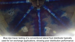
      The fluid distributors used in conventional ion exchange or adsorption applications (such as radials, laterals or nozzles) do not distribute flow effectively over the entire cross-section of the column area, especially at larger scales. Consequently, fluid flows preferentially through certain portions of the resin bed (known as ‘channelling’) while other portions remain under-utilised.

    This is evident when carrying out a tracer test using blue dye to assess the quality of fluid distribution achieved. The concentration front within the adsorbent bed spreads due to the inefficient distribution, leading to a more diffuse breakthrough curve with early leakage, reducing the efficiency of the adsorption process. This effect becomes greater as the diameter of the adsorbent vessel increases, leading to more significant reductions in performance when compared to the pilot scale and increasing the unpredictability of scale-up.

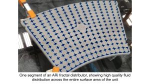
    By contrast, ARi uses proprietary fractal fluid distribution technology designed to distribute fluid flow geometrically, utilising a network of fluid channels with a high degree of symmetry. The hydraulic path that each portion of the fluid travels from the central inlet to each outlet is exactly the same, including the same number of 90° bends. This allows for a precise and uniform fluid distribution unaffected by factors such as the flow rate or the pressure drop of the flow path.

    Traditional fluid distributor types used in the chemical process industries make use of a controlled pressure drop across orifices, nozzles or screens to produce a distribution of the process fluid. However, the pressure drop through these orifices, nozzles, or screens changes substantially as the flow rate varies. As a result, a fluid distributor that may work adequately at one design flow rate will perform very poorly at any other flow rate, resulting in a very non-uniform fluid distribution.

    fluid distributors

    This is a severe disadvantage for industrial processes that depend on a plug flow distribution of the process fluid for their efficiency and performance. This problem is so severe in ion exchange applications that equipment suppliers often install two sets of fluid distributors within the same vessel – one for high rates of flow and another for operation at lower rates of flow.

    De-risking scale-up

    Fractal fluid distributors do not depend on a controlled pressure drop for efficient operation. Instead, they use their highly symmetrical structure to create a dense, uniform distribution of fluid across a surface area, which remains the same regardless of the pressure drop across the distributor. Typically, ARi fractal distributors operate with a negligible pressure drop (usually below 15 kPa or two psi) and are capable of very large turndown ratios in the flow rate of ten to one or more without any reduction in plug flow performance.

    As a result of the highly symmetrical nature of its design, fractal fluid distribution can easily be scaled to any size. Since every hydraulic flow path within a fractal fluid distributor is identical, each flow path behaves in the same way, regardless of the size of the fluid distributor or the number of flow paths. This allows fluid distributors to be scaled up to very large sizes with complete reliability and predictability.

    direct lithium extraction

    Consequently, industrial processes, such as ion exchange, adsorption and industrial chromatography, can be tested at a relatively small scale and then scaled up to a full commercial-scale implementation without risk of reduced performance. This is impossible with the other fluid distributor types used in these applications,
    which increasingly lose effectiveness at larger sizes and result in full-scale industrial performance that is inferior to that achieved on a pilot scale. The use of fractal fluid distribution thus significantly de-risks the scale-up of industrial technologies that are implemented on a very large scale, such as direct lithium extraction.

    It also saves money and time in the technology development process by potentially eliminating one or more scale-up steps (such as the relatively expensive demonstration-scale stage). For example, ARi routinely scales up industrial processes from pilot scale tests carried out in resin or adsorbent columns of 80mm (three inches) in diameter to full-scale commercial installations with vessel diameters greater than six metres (20ft) while successfully providing process performance guarantees on the resulting systems.

    ARi has already provided fractal fluid distribution technology to the lithium industry on an industrial scale, with the first DLE facility using this technology planned to go into commercial production in mid-2024.

    direct lithium extraction

    In addition to providing industrially-proven equipment and fluid distribution technology to de-risk scale-up, ARi has also developed proprietary direct lithium extraction process technology that can be tailored to various brine compositions and ion exchange technology for the polishing of lithium-rich brines to remove divalent cations and boron.

    Contact ARi to learn more about how we can help bring your lithium project to low-risk commercial-scale operation using technology and equipment solutions proven over more than 40 years at a large industrial scale.

    [ad_2]

    Source link

  • New impermeable hydrogen barrier coating system to solve 100-year-old problem

    New impermeable hydrogen barrier coating system to solve 100-year-old problem

    [ad_1]

    Triton Hydrogen has unveiled its game-changing Tritonex Hydrogen Barrier Coating System – a solution to the long-standing hydrogen containment challenge.

    Certain quests redefine the frontiers of possibility in the landscape of scientific discovery. Such is the story of Triton Hydrogen, a saga of innovation and the relentless pursuit of a solution to a 100-year-old problem. The story begins with visionary Henning Syversen, the CEO of the R&D company Triton Norway. Syversen and his team embarked on an ambitious mission: to contain the most elusive molecule in the Universe – hydrogen.

    Hydrogen, despite its promise as a clean energy source, has long been a slippery challenge. Its tiny molecular size allows it to escape even the tightest of confines, including permeating through solid steel. A group of talented scientists at Triton Norway took on the momentous challenge, combining nanotechnology, electrochemistry, and material science to contain hydrogen and help unlock its vast potential for our planet.

    Many other organisations, including scientists at world-renowned institutes, had tried and failed to create a hydrogen barrier and spent billions. Until now, nobody has succeeded in creating a 100% impermeable barrier that does not react to hydrogen.

    Grappling with hydrogen and solving the problem

    Triton’s journey took on an epic narrative in a world grappling with environmental challenges. Like alchemists of the modern age, Syversen’s team harnessed the enigmatic secrets of nano-sequencing and electro-osmosis. Their pursuit was not without trials and tribulations. Each failure was a teacher, each setback a catalyst for greater resolve. Against the odds, they developed the Tritonex Hydrogen Barrier Coating System (HBCS) – a nano-engineered marvel that heralds a new era of energy efficiency and environmental stewardship.

    Tritonex’s genesis marked the birth of Triton Hydrogen Ltd in the UK, a testament to the team’s visionary approach and commercial acumen. Tritonex wasn’t merely a scientific breakthrough but a green revolution in disguise. Tritonex HBCS may seem like an ordinary paint product which can be easily applied using all of the traditional methods from brush to spray gun, but its water-based composition holds the secret nano-ingredient.

    Tritonex has other properties too. It is electrically inert and does not react to any chemicals, which means it stops corrosion entirely – another remarkable property. Tested to temperatures of over 1,000°C, Tritonex is designed to withstand extreme temperature variations, and it is remarkably flexible and able to follow the thermal expansion and contraction movements of pipes and storage vessels. It is non-toxic, ensuring safety in handling. Its smooth surface also provides flow assurance.

    Its unique properties, including barrier efficiency, position it as an indispensable tool for the hydrogen infrastructure, storage, and transport sectors. It emerges as a universal solution, applicable across substrates from steel to composites, carbon fibre, plastic and even rock.

    Every manufacturer across the hydrogen value chain and every sector will benefit. Wherever hydrogen is involved, you need a hydrogen barrier containment solution; you need Tritonex.

    The real magic of Tritonex lies in its versatility. It can be applied manually and robotically, making it a boon for original equipment manufacturers (OEM) and field retrofitting. Tritonex has shown zero hydrogen permeation in rigorous tests, attaining its ISO 17081:2014 certification – the only barrier coating to hold this ISO – a feat that cements its place as a leader in containment technology.

    © shutterstock/Gorodenkoff

    Applications and impact of hydrogen barrier coating

    Tritonex’s applications are as diverse as they are impactful: From hydrogen storage to pipelines, electrolysis plants, shipping, and infrastructure. It’s a guardian angel in aerospace, enabling lightweight materials to construct fuel tanks and systems. For the transportation industry, it boosts safety and efficiency for vehicles using or transporting hydrogen fuel.

    The coating’s impact on the environment could be profound, preventing hydrogen leaks and curtailing the indirect global warming effects caused by escaped hydrogen molecules. Hydrogen molecules can extend the lifetime of other greenhouse gases, such as methane, increasing atmospheric warming.

    A report by Ocko and Hamburg (2022) suggests that over ten years, the warming impact of leaked hydrogen could be approximately 100 times stronger than that of carbon dioxide, highlighting the urgency of addressing this issue. This makes Tritonex not just a technological marvel but also an environmental saviour.

    Tritonex’s economic implications are equally significant. Enhancing the efficiency and lifespan of infrastructure paves the way for cost savings and reduced carbon emissions. Its retrofitting capabilities in gas pipelines and storage tanks make it a valuable asset in the energy sector.

    Additionally, its role in fuel cells, particularly high-temperature solid oxide fuel cells (SOFCs), could be revolutionary. Tritonex potentially enhances the efficiency and longevity of these cells, heralding a new dawn in fuel cell technology.

    What does the future hold for Triton?

    As Triton Hydrogen strides into the future, its legacy will continue to grow. From a visionary idea, it will blossom into a symbol of industrial innovation and environmental responsibility. The story of Triton Hydrogen is a beacon of hope, a narrative of overcoming insurmountable challenges to pave the way for a brighter, cleaner future.

    In conclusion, Triton Hydrogen’s journey, spearheaded by the indomitable spirit of Henning Syversen and his team, is a testament to human ingenuity and perseverance. It’s a story that intertwines the threads of scientific brilliance, commercial success, and ecological consciousness.

    With Tritonex HBCS, Triton Hydrogen is not just changing the game; it’s rewriting the rules, one atom at a time. This journey is more than a chapter in corporate history; it’s a blueprint for a sustainable future, a narrative that resonates with the spirit of innovation and the relentless pursuit of excellence.

    Please note, this article will also appear in the seventeenth edition of our quarterly publication.

    [ad_2]

    Source link

  • Streamline your mining operations with visual and metric data

    Streamline your mining operations with visual and metric data

    [ad_1]

    Mining companies are turning to UAS inspection technology, like the Elios 3, to prevent humans from being exposed to dangerous situations.

    Mines around the world vary in size, material, and age, but they all have the potential to pose risks for the humans who work in them. Thankfully, technological advancements are enhancing mining safety for the people who work there, with drones emerging as a game changer, particularly in confined or inaccessible spaces.

    The Elios 3, Flyability’s specialised remote visual inspection tool, revolutionises the safety and efficiency of inspections while decreasing downtime. The Elios 3 is a very flexible tool, and its applications in mining include drilling and blast assessment, exploring old workings, volume calculations and stockpile tracking, mapping, and more.

    Features and capabilities of the Elios 3

    The Elios 3 is a specialised drone created to access and collect data in the most challenging environments. It has a collision-tolerant cage along with special flight monitoring settings that help it withstand and correct impact in confined spaces.

    The drone also carries a unique set of capabilities in that it can simultaneously gather visual and LiDAR data.

    The drone’s LiDAR data, particularly with the Surveying Payload, is accurate to one centimetre. The Ouster Rev 7 sensor ensures high-quality results, gathering 1.3 million points per second with superior photon sensitivity, empowering surveyors with reliable and precise data for various projects.

    Ensuring safety in mining

    Traditionally, mining has been a hazardous occupation where workers must enter dangerous or unstable environments on a regular basis. They encounter heat exposure, unpredictable air movement, and unstable structures.

    To mitigate these risks, mining companies can use drones to do the initial inspection and gather data to assess possible risk.

    The Elios 3 aids in determining safe entry and conducting regular surveys of different environments over time.

    It can even be used as an emergency response, thanks to fast deployment, and its ability to gather visual and LiDAR data for locations beyond visual line-of-sight.

    Access to unreachable areas

    Each mine presents unique challenges, and drones can provide unparalleled access to areas previously unreachable. This could include reaching orepass hangups or fall-of-ground locations.

    Drones present an ideal tool for accessing places that were previously unreachable. They can fly and work at height, while specialised drones can also enter confined spaces to gather information and conduct surveys. This is particularly useful when working in potentially hazardous environments, such as surveying old workings.

    This improved access to an area with a drone can unlock new information. Drones can be flown through ventilation systems to check the condition of pipes and plan maintenance, or similarly down blocked pipes and tunnels that cannot be safely reached by people, traditional laser scanners, or cable-mounted cameras.

    The Elios 3 drone can fly beyond the line of visual sight, and the pilot can rely on the LiDAR live map and video feed to guide the drone into tricky locations measuring as small as 50x50cm. This ability to reach new areas makes it a valuable tool for improving access to more of a mine with greater ease and safety.

    Data quality

    The LiDAR data gathered with a drone can be used for various projects, from stockpile tracking to convergence monitoring or inspecting old workings.

    The LiDAR data gathered with the Elios 3’s specialised Surveying Payload is accurate to one centimetre using the Ouster Rev 7 sensor, which has ten times higher photon sensitivity than the Elios 3’s standard LiDAR sensor.

    The Rev 7 provides incredibly high-quality results in shorter flight times, empowering surveyors to analyse their results with confidence in the data accuracy.

    Efficiency and decision making

    The quick deployment, high-quality data, and flexible operation make the Elios 3 a highly efficient solution. There is no need to set up scaffolding and PPE or implement extended shutdowns. A ten-minute flight can cover an ore pass that traditionally takes hours or even days.

    One customer praised the Elios 3, stating: “To get to some of the places we send the drone, you’re pulling a $2m loader off its job, strapping a scanner onto it and sending it somewhere remotely. This becomes a 15-minute job with Elios.”

    About the Elios 3

    Elios 3 is the outcome of four years of extensive engineering work. The integration of FlyAwareTM – a proprietary SLAM engine that works in combination with a brand-new LiDAR payload – enables significant upgrades in terms of performance, versatility, and stability.

    Elios 3 is designed to be used by anyone on your team, indoors, in complete darkness, and no matter the dust.

    Its SLAM-based stabilisation algorithm, powered by the fusion of three VIO cameras and the LiDAR, catches the tiniest unpredictable movements of the drone and instructs the flight controller to compensate for it, allowing for the drone to float in the air still as a stone, even in the toughest conditions.

    This stability and other ease-of-use features make the Elios 3 incredibly easy to operate, so pilots from all skill levels will succeed at performing complex missions with almost training.

    The quick hits

    •    Accessibility: Excels in GPS-deprived, dusty, and dark
    environments reaching small, inaccessible areas that
    traditional tools and other UAVs can’t access.
    •    Safety: Enables scanning and inspection of indoor
    assets before human entry.
    •    Data quality: Capture centimetre-accurate scans, with
    4k videos and 12 MP images
    •    Efficiency: Inspect your assets in just a fraction of the
    time compared to traditional methods.

    The Elios 3: Bringing higher quality data results to mines globally

    The Elios 3 stands out as a key tool for bringing safer, higher quality, and more efficient data collection and results to mines worldwide.

    Tailored for complex environments, its modular design ensures ongoing capabilities as new payloads unlock additional applications.

    Witness the Elios 3 in action by contacting our team to organise a demo at a site near you.

    Please note, this article will also appear in the seventeenth edition of our quarterly publication.

    [ad_2]

    Source link

  • Growing value through discovery in the Balkans

    Growing value through discovery in the Balkans

    [ad_1]

    Terra Balcanica, a junior Canadian explorer of critical metals, eyes untapped opportunities at Europe’s doorstep.

    What do you get when you combine a millennia of mining history, two resource extraction-friendly European jurisdictions with clear paths to permitting mineral exploration concessions, a knowledgeable workforce, and a continent starved for critical metallic resources?

    Add to that a world class metallogenic expertise and a plethora of innovative geochemical and geophysical techniques that helped define grassroot drill targets in less than a year, all of which proved to be mineralised. Welcome to Terra Balcanica Resources Corp. and its ~350km² polymetallic portfolio of the Western Balkan Peninsula.

    Terra Balcanica is a junior Canadian explorer of precious and base metal resources in Europe’s front yard, where it has been advancing five exploration licenses in Bosnia and Serbia. Listed on both the Canadian Securities Exchange (CSE:TERA), and the Frankfurt Stock Exchange (FRA:UB1), the company has made strides since acquiring its flagship land package in eastern Bosnia in 2020.

    Called the Viogor-Zanik Project, the 215km² aggregate of licences surrounds the operation Sase mine (Mineco Ltd.) with an annual production of 350,000 tonnes of Pb-Zn-Ag+/- Sb concentrate, and is centred upon a mining district mined as far back as the Roman times when it was known as Argentaria.

    A multidisciplinary approach to target definition

    In slightly over three years, Terra’s technical and field teams have mapped, sampled, surveyed, and drilled two out of three highly prospective target zones within the only Oligo-Miocene manifestation of the highly prolific Western Tethyan orogen in Bosnia and Herzegovina.

    The belt, whose mapped southeastern extension reaches Afghanistan via the Balkans, Turkey, and Iran, features world class porphyry copper and epithermal gold-silver deposits (Sarcheshmeh, Sari Guni, Kişladag, Skouries, Olympias, Trepca), and terminates right at Terra Balcanica’s feet as the metalliferous Srebrenica Magmatic Complex.

    Here, a meticulously systematic approach of layering dozens of data sets obtained by months of lithological and structural mapping, combined by those gained from airborne geophysics, satellite multispectral terrain surveys, and thousands of rock and soil chemical assays revealed two genetically distinct, yet equally attractive targets worth drill testing.

    terra balancia, mineral exploration

    And drill, Terra did. Both the Cumavici and Brezani targets were tested to the tune of over 2,000m of diamond drilling, respectively, with attractive metal grades intercepted close to surface but the story does not stop with Bosnia.

    In neighbouring Serbia and another mining heavyweight of Europe (e.g. Timok District), Terra Balcanica operates two exploration concessions in the historic Rashka district, once home to many a medieval Saxon miner employed by the Serbian kings of the epoch.

    Here, the Ceovishte and Kaludra licences comprise a 130km² land portfolio rich in Zn-Pb-Ag-Au-Cu showings. Particularly interesting is the former, where Terra’s geologists have collected high-grade precious metal samples on-surface that overlay historical workings featuring highly enriched vein-hosted mineralisation. None of the Serbian targets have been drill tested to date, and remain Terra’s immediate focus for the 2024 Phase III campaign.

    As only the second (foreign) mineral explorer in Bosnia, Terra Balcanica is poised to capitalise on regional early-mover opportunities, while remaining a nimble, agile, and cost-effective explorer of choice in SE Europe.

    For many at Terra, discovering mineable resources needed by the world of tomorrow is not just a self-evident mission but an homage to the proud, century-long history of mining in Europe.

    The art of discovery

    Ours is a disciplined and creative team of mining professionals that has demonstrated an ability to make discoveries in places overlooked or abandoned by others, and to leverage these forgotten or neglected gems as incubators of the mining continuum, and value creators for our shareholders.

    Whether it is systematically rehashing volumes of archived data sets, modelling newly acquired geophysical data, or rapidly ground-truthing the rugged vast expanse of the Western Balkan Peninsula aimed at targeting the ‘sweet spots’ – discovery is in our geological DNA. Our leadership group and technical team are fully vested and singularly committed to this goal.

    The Čumavići target

    Within the Viogor-Zanik Project of eastern Bosnia and Herzegovina lies the Čumavići target. This shallow, high-grade, polymetallic target area extends for over seven kilometres NW/SE through the project. Tens of mineralised showings which returned assay grades up to 128 g/t silver and 20% zinc are visible alongside historic mining works. Silver-zinc-manganese-antimony all show anomalism in soil geochemistry, coupled with linear magnetic low responses (indicative of possible host structures).

    Terra has completed diamond drilling at two locations and discovered polymetallic veins and breccias returning assay grades up to 11m at 505 g/t silver equivalent (gold-silver-lead-antimony-zinc recalculated to the value of silver) in 2022 drillhole CMVDD004.

    Individual drill core samples have returned values as high as 1,420 g/t silver over 1.7m and 31% combined lead and zinc over 90cm. Terra has only scratched the surface of the Čumavići story and is excited to continue drilling in 2024. As more mineralisation is discovered within the Čumavići corridor it is worth noting the proximity of Terras discovery to the operating Sase Mine, actively depleting their ore reserves.

    The Brežani target

    Just 11km to the southeast, within the Viogor-Zanik Project. lies the Brežani target. A greenfield discovery in 2021, Brežani presents a kilometre-scale mineralised hydrothermal system first identified as a large magnetic anomaly, coupled with over 700m strike length of elevated gold in soil. Drilling at the target has revealed not only that the gold on surface extends down to 88m (results from drillhole BREDD002) but is also host to strong epithermal mineralisation at depth.

    The gold in drill core was consistent at 0.5 g/t, reaching up to 1.5 g/t for six metres. Brežani represents the only gold mineralised skarn (a calc-silicate rock) in Bosnia and Herzegovina and is set to grow with further drilling.

    terra balancia, mineral exploration

    Recently discovered and extensive epithermal mineralisation encountered downhole shallows to the east-northeast, where a similar element assemblage of silver-arsenic-antimony is present within rock and soil samples from a topographic low, coupled with a magnetic low. This offers shallower drill targets for this prospective polymetallic mineralisation.

    Prospective work at Ceovishte

    Terra Balcanica also operates in neighbouring Serbia, where it holds 80km² of highly prospective land in the historic Raška mining district. The Ceovishte Project represents a previously overlooked high grade gold-copper target with surface rock chip assay results up to 64 g/t gold and 2% copper.

    Samuel Vaughan, MSc – Terra’s project geologist

    A Master of Science graduate of the Camborne School of Mines, Samuel Vaughan is a geologist specialising in mineral exploration. Having spent four seasons working in the high Arctic of Greenland, he joined Terra in 2021 and commenced target generation.

    After systematic integration of the thousands of geochemical data points and layers of geophysical evidence, Samuel has been managing day to day operations across the exploration licenses.

    Digitising historic data from the 1950s Terra has identified notes of bonanza gold and silver grades just 30m below the surface, which offers a compelling target. Terra is excited to commence drilling at Ceovishte in 2024, testing depth extensions to high grades observed on surface and ground truthing historic records of bonanza gold and silver.

    Away from these historic workings, over 300 soil samples were collected and analysed by Terra, revealing a previously unknown area of Au-Bi-Cu-Te anomalism over 900m in strike length. This signature could represent a sub-cropping copper porphyry deposit and will require more detailed geological mapping, geochemical sampling, and possible geophysics to assist in imaging the subsurface prior to exploration drilling.

    What is in store for 2024?

    As a regional Balkans explorer, Terra Balcanica has proven capabilities of identifying prospective projects and discovery mineralisation. Being on the doorstep of Europe, and given the demand for critical metals such as lithium, Terra has identified a prospective area and is looking to move into the battery metal exploration space.

    terra balancia

    The western Balkan Li-B (lithium-boron) metallogenic zone spans for over 1,500km through Croatia, Bosnia and Herzegovina, Serbia, and Kosovo along its path to Turkey to the east. The Serbian portion of the zone hosts Rio Tinto’s Jadar Project, a sediment hosted lithium-boron deposit discovered in 2004 hosting indicated resources of 85.4Mt at 1.76% Li2O and 16.1% B2O3 with further inferred resources of 58.1Mt at 1.87% Li2O and 12.0% B2O3 as of 31 December 2021.

    Terra Balcanica is excited to commence its lithium exploration journey in 2024 and add value to an already diversified portfolio of assets.

    In addition to a wealth of up-to-date information found on the corporate website www.terrabresources.com, the company is active and regularly disseminates corporate updates through our social platforms.

    Sustainable mineral exploration practices

    At Terra Balcanica, we emphasise responsible engagement with local communities, municipal governments, and key stakeholders. The company is committed to proactively implementing Good International Industry Practice (GIIP) and sustainable health, safety, and environmental management.

    We are particularly proud of our workplace safety and environmental protection record that include safety trainings, baseline environmental surveys, and regular community initiatives. The goal is to have our employees return to their families safely while maintaining a minimal environmental footprint.

    [ad_2]

    Source link

  • How the EPIQC project is empowering the quantum computing revolution

    How the EPIQC project is empowering the quantum computing revolution

    [ad_1]

    The EPIQC project is helping to take the quantum world forwards, both in terms of academic research and in terms of awareness.

    In the contemporary world of science and technology, quantum computing stands as a beacon of potential, promising to usher in a new era of computational power and problem-solving capabilities, far beyond the reach of traditional computing. At the forefront of this technological revolution is the Empowering Practical Interfacing of Quantum Computing (EPIQC) project, led by the University of Glasgow, with significant funding from the Engineering and Physical Sciences Research Council (EPSRC).

    This project is not just another step in advancing quantum computing; it represents a pivotal shift towards integrating this nascent technology with the more established realm of Information and Communication Technologies (ICT).

    Quantum computing and the future

    Quantum computing, with its roots in the principles of quantum mechanics, operates fundamentally differently from traditional computing. While conventional computers use bits to encode information in binary forms of 0s and 1s, quantum computers employ quantum bits or qubits.

    These qubits harness the phenomena of superposition and entanglement, allowing them to exist in multiple states simultaneously, thereby offering exponential growth in computing power. This leap in computational capabilities holds immense potential for various fields, including cryptography, material science, pharmaceuticals, and complex system modelling.

    However, despite its promising future, quantum computing faces significant challenges, particularly in transitioning from theoretical models and lab-scale experiments to practical, real-world applications. One of the primary obstacles is the lack of a comprehensive infrastructure that facilitates interaction between quantum computers and existing ICT systems. This gap significantly limits the applicability of quantum computing technologies in everyday devices and networks that form the backbone of today’s digital world.

    Fig. 1: A state-of-the-art quantum computing cryostat, key to the
    EPIQC project’s ambition to develop interfacing concepts between
    room temperature (that’s 20 °C, corresponding to 300 Kelvin)
    ICT and quantum hardware. Operating at 10 millikelvin (mK), this
    hardware reaches temperatures 100 times colder than outer space.
    The low temperatures are required to screen the quantum computer
    from (thermal) noises, requiring researchers to carefully engineer
    the extreme frontiers of quantum computation and connectivity to
    the outside world/users.

    The EPIQC project’s work

    Addressing these challenges, the EPIQC project aims to bridge the divide between quantum computing and ICT. Over a span of four years, researchers from academia across the UK are collaborating to co-create new methods and technologies that could integrate quantum computing into the broader ICT landscape.

    The project is set to explore and develop solutions in three critical areas: optical interconnects, wireless control and readout, and cryoelectronics. Each of these areas is crucial for overcoming the barriers that currently hinder the scalability and practical application of quantum computing.

    In pursuing quantum computing advancements, researchers grapple with the challenge of limited cooling capacity at temperatures approaching millikelvin. At these levels, essential for quantum processors to function, only a tiny amount of heat can be shed, making efficient thermal management crucial.

    The quantum processors depend on high-precision signals that must be delivered with exacting accuracy and without delay. Even slight latencies can disrupt quantum states and degrade computational performance. The traditional method of scaling up – using more fixed wires to connect room-temperature machinery to ultra-cold quantum components – is proving unscalable.

    The additional wires introduce extra heat, which the already strained cooling systems cannot handle, thus hindering the growth of quantum systems. Therefore, clear and efficient solutions are needed that strike a balance between maintaining near-zero temperatures and providing fast, accurate signal transmission for quantum computing to reach its potential.

    Low temperature of 10 millikelvin. Qubit control and readout system alternatives are conventional control
    electronics, ultra-fast and low-power SFQ devices, cryoCMOS technology, wireless sources, or optical
    control systems. EPIQC focuses on the latter three interfacing concepts. Key requirements are maintaining
    the Quantum processing unit (QPU) at ultro-low temperatures, by carefully engineering the heat loads.

    In the dynamic world of quantum computing, the EPIQC project emerges as a Centre of interfacing innovation, guided by the leadership of Professor Martin Weides and Professor Hadi Heidari from the University of Glasgow. Professor Weides articulating the project’s essence, said: “We are genuinely excited about the EPSRC’s support for the EPIQC project.”

    “This project represents a significant step in bringing together leading researchers in quantum technology and ICT from across the UK. Our goal is to tackle some of the challenging issues at the interface of quantum computing and ICT. With our combined expertise and access to state-of-the-art facilities, we’re optimistic about developing a robust network for collaboration. This will not only produce exciting results but also help in shaping the future roadmap for quantum computing interfaces.”

    Echoing this sentiment, Professor Hadi Heidari highlights the project’s pioneering approach, combining academic rigor with industry insights. Professor Heidari said: “The EPIQC project marks a first of its kind in the quantum computing field, focusing on the co-creation between quantum computing and ICT researchers, along with industry involvement.”

    “It’s exhilarating to have some of the top experts from academia as part of our team from the onset. We’re venturing into a rapidly expanding field, and our work could lead to transformative changes. Being at the forefront of this venture, supporting the UK’s role in quantum computing excellence, is both a privilege and a responsibility.”

    Project collaboration

    The EPIQC project’s academic collaborators include the Universities of Strathclyde and College London, the National Physical Laboratory, the National Quantum Computing Centre and the Harwell Campus, along with the Universities of Birmingham, Lancaster, Southampton, and King’s College London.

    These institutions bring a wealth of knowledge and expertise in quantum mechanics, photonics, and ICT. Complementing the academic expertise, industrial partners like Oxford Instruments, Leonardo, NuQuantum, and BT provide practical insights and technological advancements, fostering an environment where theoretical quantum computing concepts are translated into tangible, innovative applications.

    Started in 2022, EPIQC has already begun building a community around quantum computing and ICT interface. The project has hosted several meetings, bringing together principal investigators, PhD students, postdoctoral research associates, and industry experts to discuss and define joint feasibility studies within each of the three key areas. These meetings have not only fostered collaboration and networking but have also laid the groundwork for the research directions that the project will take in the subsequent years.

    The progression of the project is marked by a series of critical meetings, each highlighting the ongoing advancement and shifting research emphasis. At the inaugural gathering in Glasgow, establishing the foundation for the project, the principal investigators defined the strategic course, scope, and feasibility for each of the project’s three main pillars.

    This meeting was essential in setting the stage for all future research and development activities. The subsequent meeting at the National Physical Laboratory broadened the project’s reach. It included valuable contributions from PhD students and Postdoctoral Research Associates, offering fresh perspectives on the project’s progress and the challenges encountered.

    It also included the interaction with other QC-ICT consortia, exploring mutual interests, and potential partnerships. Assessing the progress of the project’s various undertakings, with a particular focus on the smaller explorative projects, helps strategise for forthcoming industrial collaborations. It also entailed critical future planning, ensuring that the project’s trajectory remains in line with its overarching goals.

    The three pillars of EPIQC

    The EPIQC project, underpinned by its three specialised pillars, is advancing the frontier of quantum computing. Each pillar, led by a dedicated team of experts, targets a unique aspect crucial for integrating quantum systems with contemporary technology.

    The first pillar concentrates on optical interconnects, utilising photonic integrated circuits, fibre optics, and electro-optical devices. The aim is to develop technologies that enable efficient operation and control of large qubit arrays, surpassing the constraints of traditional electronics. This effort focuses on achieving greater bandwidth and scalability, leveraging the minimal heat contribution of optical fibres.

    The second pillar explores the potential of wireless technology in quantum computing. It seeks to replace traditional coaxial cables with a versatile, cryogenic wireless control and readout system. This innovative approach aims to manage hundreds of qubits simultaneously with minimal interference, using advanced multiplexing techniques to prevent decoherence, a critical factor for scalable quantum systems.

    Cryoelectronics forms the third pillar, focusing on developing cryogenic CMOS, FPGA, and low-noise amplifiers. These components are designed to function effectively in the extreme cold, essential for quantum processors, and are integral to the seamless operation of both optical and wireless systems in the quantum realm.

    Particularly noteworthy is the role of CryoCMOS technology. It stands out for its minimal heat dissipation and ability to function in the deep-cold environments necessary for quantum computing. Its integration into quantum systems is vital for reducing latency and streamlining signal processing, making it a key enabler for scaling up quantum computing. Moreover, CryoCMOS technology facilitates complex, on-chip error correction and control, enhancing the precision and reliability of quantum operations.

    Ensuring the success of these innovations is a rigorous verification process. It involves thorough testing of components to meet performance standards, particularly in terms of thermal management and scalability. Moreover, careful packaging and thermal management strategies are employed to safeguard the system from thermal and electromagnetic disruptions.

    Fig. 3: Secondary school students engrossed in a live demonstration of cryogenic quantum computing hardware, as part of EPIQC’s outreach program aimed at inspiring the next generation of scientists with hands-on experience.

    In addition to these collaborative efforts, the EPIQC project has been active in outreach activities. These include supporting an annual Quantum Technology School for secondary students, participating in industry forums, and presenting at various summits and industry showcases including the UK National Quantum Technologies Showcase 2022 and 2023.

    This includes the assembly of a levitation train based on the principles of superconductivity and the mathematical concept of a Mobius strip to provide the public with an interactive understanding of the properties of superconductors, a key element in the advancement of quantum computing, along with online videos on quantum technologies on social media.

    The EPIQC project’s approach extends beyond research, emphasising networking and education. Regular workshops and events foster a dynamic exchange of ideas among scientists, policymakers, and industry leaders. Additionally, educational outreach initiatives are designed to raise public awareness about the impact and significance of quantum computing.

    EPIQC project

    Please note, this article will also appear in the seventeenth edition of our quarterly publication.

    [ad_2]

    Source link

  • Building on battery recycling success

    Building on battery recycling success

    [ad_1]

    Roger Miksad, President of Battery Council International, explains how the path to sustainability will need to include existing battery recycling as well as the development of new batteries.

    The United States is experiencing a battery-powered revolution in transportation and grid energy storage that promises enormous environmental and economic gains. Lithium-ion, advanced lead-acid, flow, sodium-ion, and emerging battery chemistries have enabled the rise of electric vehicles (EVs) and are supercharging the transition to renewable energy sources. Continued innovation promises even greater capabilities.

    But with any revolution comes disruption and risk. As usage explodes, we must ensure this battery boom does not translate into a battery waste crisis.

    Fortunately, the road to safer and more sustainable battery lifecycles has already been paved by the nation’s most recycled product: The stalwart lead battery. The lead battery industry operates an unparalleled collection and recycling system. For over 30 years, lead batteries have been recycled at a nearly perfect 99% rate, far outpacing any other consumer product, according to a recent recycling rate study.

    This was not by accident but rather through purposeful policies and industry commitment to circularity. Lead battery recycling diverts hundreds of millions of pounds of lead and plastic from landfills annually and supplies roughly 90% of all lead used domestically for new battery production.

    Other battery industries should embrace and replicate lead battery recycling’s core strategies of consistent labelling standards, widespread free consumer collection opportunities, prohibitions on improper disposal, and industry-funded transportation and processing networks.

    Adopting these policies broadly across lithium-ion and other emerging battery chemistries is essential to continued innovation. It will ensure sustainable growth of a robust domestic battery manufacturing and recycling industry rather than trading one environmental challenge for another.

    Building battery recycling into the foundation

    The lead battery industry’s recycling achievements trace directly back to forward-looking policies pursued by the industry starting in the late 1980s. Businesses recognised recycling would need to be designed into our products, manufacturing processes and collection channels – not bolted on after the fact.

    With encouragement from the U.S. Environmental Protection Agency (EPA) and environmental groups, battery manufacturers and recyclers found consensus on legislation that ensured collection opportunities were available wherever batteries were sold. Within a decade, nearly 40 states representing over 80% of the population enacted laws embracing these core principles:

    • Ban improper disposal in landfills to prevent releases;
    • Require all battery retailers also accept returns from consumers;
    • Mandate that manufacturers arrange for transportation and recycling; and
    • Incentivise consumer returns through refundable core charge deposits.

    These simple but purposeful policies completely reshaped consumer collection channels and recycling efficiency. Within a few short years, lead battery recycling rates jumped from below 80% to consistently above 99%.

    The enactment of these forward-leaning policies positioned the lead battery industry to simultaneously expand domestic manufacturing and increase the use of recycled materials. Today’s robust recycling network supplies more than 85% of lead metal demand for new US battery production and powers a $26bn industry supporting 92,000 jobs, according to a recent economic impact report.

    Supporting safe collection of all chemistries

    With today’s diversity of battery chemistries serving vastly different applications, uniformly imposing rigid legislative mandates risks unintended consequences. We must take care to avoid disrupting what works – like lead battery recycling – while thoughtfully extending proven policies to emerging chemistries.

    Lithium-ion batteries help power devices and technologies previously unimaginable but pose fire and safety risks if mishandled, especially during recycling. As usage soars over the next decade, inadequate sorting and recycling infrastructure threatens contamination of existing lead battery streams. Such cross-contamination can decrease process efficiencies, compromise the quality and safety of recovered materials, and endanger collection workers.

    A key component of the safe and profitable operation of any metals recycling operation is efficiency and consistent throughput. Battery Council International’s recycling members process more than 160 million batteries per year for recycling across North America, with hundreds of millions more processed around the world. Across the major recycling facilities in the US, a typical battery recycling facility can process 80 or more vehicle batteries per minute.

    © shutterstock/KimTieng Tow
    Many recycled batteries are recycled into lead, ready for further use

    The lead battery recycling process is a highly specialised process honed over the decades to be highly efficient when there is a steady and clean supply of used batteries. This efficiency is one of the core drivers of lead batteries’ unparalleled recycling success. However, when incompatible materials, such as lithium batteries, enter the lead battery recycling stream, they can reduce the quality of the recovered materials.

    Most importantly, contamination of the lead battery recycling stream poses a serious threat to employee safety. Lithium batteries dramatically increase the risks of fire and explosion posed to facilities and workers if they inadvertently find their way into the lead recycling process. This is, in large part, due to the high energy potential of these batteries combined with their relatively low tolerance for physical damage, such as the crushing that has long been a part of the proven lead recycling process.

    Every lead battery recycler with whom BCI works catches multiple lithium batteries every day, and all have experienced unfortunate incidents when lithium batteries slipped through the rigorous inspection processes.

    The sorting and identification process is becoming ever more difficult as more lithium batteries are designed to mimic lead batteries, and volumes are increasing. Our members remain vigilant about their recycling streams and, in the event of lithium contamination, can often successfully mitigate any negative effects. But no facility can solve this challenge alone; it’s up to public officials and private sector participants to work together to ensure everyone is doing their part to protect public health and safety.

    Further complicating matters, the introduction of additional ‘ride-along’ contaminants requires the recycler to perform additional time-consuming and expensive metallurgical refining steps to achieve the necessary quality of recovered metal. This increases the carbon emissions and energy consumption of the process and increases the amount of waste by-products produced by the process.

    The 99% recycling rate of lead batteries is a huge point of pride for our industry, and we want to ensure the broader disposal and recycling infrastructures for other battery chemistries do not undercut the sustainable model we have built over the decades.

    The experience of lead battery recyclers is not unique. The contamination of any recycling input stream with incompatible or potentially dangerous materials creates real challenges to the quality of the recovered materials, the positive environmental impact, and the participation rate among businesses and consumers across the supply chain.

    Efficient and safe recycling processes are good for everyone. That’s something we’ve learned firsthand in the lead battery industry, and we’re eager to help apply our lessons learned to other areas.

    Battery chemistry labelling standards and guidelines are needed

    Protecting America’s current and future recycling infrastructure requires consistent and standardised labelling to enable proper identification and sorting between distinct chemistries and applications. BCI supports the adoption of clear, human-readable sorting labels on all batteries—ideally embracing a globally standardised format. Existing voluntary standards such as IEC 62902 can provide a foundation for industry, government, and NGOs to establish labelling schemes.

    © shutterstock/Phoenixns_2239074539
    Battery waste is often an environmental hazard, making recycling of batteries of even greater importance

    Currently, there is no mandate in the US for all battery chemistries to use a uniform human-readable identification for battery chemistry. This has created problems in the marketplace because batteries of similar size can be readily confused and are frequently placed into the wrong recycling collection stream. EPA should consider how best to ensure that consumers and collection network participants have the information needed and the opportunity to direct each type of battery to the right collection stream.

    Battery labels should have a consistent and simple marking (e.g., a colour-coded, three-chasing arrows loop) across all battery chemistries to encourage and aid recycling. At a minimum, recycling and chemistry markings should address three primary goals. In order of priority, they are:

    1. Instructing consumers to keep batteries out of the trash and curbside recycling, and are directed to dedicated battery recycling networks where available;
    2. Providing consumers and recycling network employees with human-readable information to enable the sorting of used batteries among major chemistry families (e.g. Pb, Li-ion, Ni-Cd, Ni-MH, and Li-metal); and
    3. If appropriate within a chemistry family, inform recyclers of the unique features, components, and/or constituents of the batteries for recovery (e.g. cathode material).

    As battery labelling standards are adopted, it is important those standards be consistent across chemistries sold on the US market, regardless of the country of origin. Requirements imposed only on domestic manufacturers will fail to address the problem considering the dominance of foreign manufacturers of lithium and other battery chemistries. Labelling standards must be identifiable and enforceable by US Customs Inspection officials to ensure that batteries entering the US market are compliant and do not pose additional hazards.

    Battery labelling best practices should also consider, in addition to a recycling and chemistry disclosure marking, additional safety and hazard information to inform users and recyclers of necessary storage requirements, fire hazards, and other information. OSHA and CPSC labelling regulations provide ample guidance and foundation.

    Labelling is not a panacea, however, and even reliable labelling cannot eliminate risks entirely without additional safeguards built into collection and transportation channels. All participants in the collection and return chain must be trained in the proper sorting and segregation of chemistries and in the safe handling and transportation of used batteries.

    Closing the loop through circularity

    With sound policies and industry initiative, we can replicate the circularity success of lead batteries across additional chemistries. However, the unique residual value of recyclable lead components may not directly transfer to other battery types.

    Most lithium-ion recycling is unprofitable today, without subsidies or processing fees. Achieving true circularity requires continued technological innovation to improve economics. Industry must collaborate with regulators in pursuing pragmatic advancement of both recycling and collection infrastructure. With patience and purpose, commercially viable recycling pathways can be developed for emerging applications.

    The alternative is simply unacceptable: Deepening and growing the known environmental and safety threats. We must, therefore, learn from the proven lead battery industry playbook to enable safe battery disposal across the energy storage landscape.

    A battery waste crisis is not inevitable. Averting it requires intentional action, beginning today. With foresight now towards sustainable collection and economically viable reprocessing, our clean energy future remains a path towards circularity.

    Please note, this article will also appear in the seventeenth edition of our quarterly publication.

    [ad_2]

    Source link

  • Closing the sustainability loop in the magnet industry

    Closing the sustainability loop in the magnet industry

    [ad_1]

    With its new approach to permanent magnets, PM-Wire magnets, the Advanced Magnet Lab is enabling the use of lower-cost materials, novel design and manufacturing, and revolutionising motors and generators to decommoditise the magnet supply chain.

    Magnets are at the heart of products like electrical machines (motors and generators), which are, in turn, used in virtually every sector of society – energy, manufacturing, consumer products, and transportation. Magnets are a critical component in areas like defence, used for instrumentation, weapons, and vehicles (land, air, and sea).

    Today, China dominates the market, controlling over 85% of the magnet market. China’s vertical integration of cheap labour, raw materials, and unsafe environmental standards has resulted in a high barrier to market entry for competitors worldwide. Historically, companies entering the magnet market could not compete with China and sustain a magnet business.

    The Advanced Magnet Lab (AML), Melbourne Florida,  has taken a completely different approach. Breaking China’s stronghold requires breakthrough innovations for enabling a sustainable magnet supply chain to re-invent technology and transform the industry.

    To do this, AML is innovating all aspects of the supply chain, including materials, magnets, magnet manufacturing, and the largest magnet market electrical machines. This new approach will result in a sustainable and decommoditised magnet supply chain.

    The conventional approach to the magnet supply chain is wrong
    While scale has increased and materials have improved, the materials used to make magnets, magnet technology, and the methods for manufacturing magnets and how the magnets are used in applications have been the same for decades.

    Conventional magnets are complex to assemble and limit design engineers to configurations which are not optimised for performance and cost of the end-use products, such as electrical machines. Magnets are produced in blocks, then cut into small pieces, and sold as a commodity.

    Conventional magnets are restricted in shape, size, and mostly single-direction magnetisation, meaning the largest market motors are limited to traditional north-south magnet pole designs. This requires dozens, hundreds, and sometimes thousands of magnets in an assembly. With very strong magnetic fields, assembly into a motor is complex and costly.

    Furthermore, the trend is towards higher-grade and better-performing magnet alloy compositions, requiring expensive rare earth elements (REE) and an unclear intellectual property landscape.

    The AML market approach

    AML’s business model is to not make conventional ‘me-too’ magnets. Historically, companies entering the magnet supply chain could not compete and sustain their business due to China’s stronghold and ability to manipulate the market.

    A magnet business can only be sustainable if the magnet product provides the magnet user with a better solution.

    A solution that not only competes with but out-competes the conventional Chinese approach. AML’s approach to the market is unique. AML focuses on what matters. Improving the performance and lowering the cost of the end-use product.

    The AML technical approach

    Unlike the conventional approach, AML’s approach provides engineers with a whole new set of tools to enable fully optimised product designs. The approach can be used with existing sintered magnet alloys and opens new markets for non-sintered and non-REE alloys. Electrical machine designs can now be fully optimised for performance, including efficiency, torque, mass, operating temperature, and ease of assembly.

    To do this, AML is addressing and therefore innovating every aspect of the magnet supply chain, which will result in a decommoditised market. This includes the magnets, magnet materials, magnet manufacturing, and electrical machines.

    pm-wire magnets

    PM-Wire magnets

    AML has developed and patented a manufacturing process for sintered, non-sintered, and non-REE magnets called PM-Wire™. PM-Wire magnets are manufactured using a semi-continuous, high-yield and high-rate manufacturing process with flexibility in the magnet length, cross-section, magnet shape and magnetisation direction.

    PM-Wire is the ideal way to produce magnets; it uses a ‘wire-like’ manufacturing process where all the critical process parameters can be adjusted and precisely maintained for any magnet alloy type, including non-REE materials.

    The manufacturing process involves filling thin-walled tubes with permanent magnet alloy powder, powder densification, and applying a magnetic field with a preferred direction of magnetisation. The tube is then size reduced to its specified cross-sectional (i.e., square, rectangular, pie-shape), rolled into its final shape (i.e. straight, curved, rings, helixes), and then finally magnetised.

    For non-sintered magnets, the tube becomes the magnet powder containment and a means to optimise the packing density which optimises the magnet performance. It also eliminates the need for a bonding agent, further optimising the performance. The tube becomes the magnet jacket, resulting in virtually an unbreakable magnet, and the jacket seals the magnet, preventing oxidation and corrosion.

    The PM-Wire product line currently includes three unique configurations, which are named based on the type of magnetisation direction: PM-UNIFORM™, PM-AXIAL™ and PM-360™.

    PM-UNIFORM™

    Consisting of straight, curved, ring, or helical magnets with transverse or radial magnetisation, these can be produced in metre lengths and offer lower cost assembly and reduced part count.

    PM-AXIAL™

    Curved magnets with axial magnetisation, allowing rotor topologies with breakthrough benefits. The PM-AXIAL provides increased performance, reduced mass, and ease of assembly for any given alloy or provides equivalent performance using lower grade/cost alloys, including non-REE alloys.

    PM-360™

    Straight, ring, or helical magnets with ‘continuously changing magnetisation direction’ (continuous Halbach array), PM-360 offers increased performance, significantly reduces part count, reduces mass, and greatly simplifies assembly. These can be produced in straight metre lengths, ring, or helical shapes and offer significantly lower cost assembly and part count.

    The magnet alloys

    The AML approach improves the application performance of all existing magnet alloys and enables the use of new, lower-cost alloys including REE-free alloys.

    Today, REEs are an essential and critical aspect of the magnet supply chain. REEs are not rare at all; they are called rare due to the difficulties in extracting and separating the metals from the ore. These elements rarely exist in pure form; they are usually found mixed with other minerals, making them costly to extract into the pure form of REE oxides needed for magnets.

    There are 17 REEs, with those categorised as the critical magnet REEs being neodymium, praseodymium, dysprosium, and terbium. Other non-critical REEs to be considered for magnets are lanthanum and cerium.

    Magnet alloys and key performance drivers for electrical machines

    Magnets are produced from alloys such as neodymium iron boron (NdFeB) which can have differing compositions based on a specific application requirement. An example NdFeB composition would include neodymium praseodymium (NdPr) (29%), iron (68%), boron (1.2%), aluminium (0.3%), niobium (0.5%), dysprosium (1%). The differing compositions result in magnet grades (i.e., N40, N40H, N45, N48SH).

    The higher the grade, the greater the performance and the higher the cost. To understand the basics of a magnet grade and associated performance there are a few key parameters which strongly depend on temperature, the magnetic remanent field (Br), coercivity (Hc) and energy product (MGOe). For example, NdFeB N48SH has a Br of 1.2 tesla, Hc of 8.1 kGauss (kG) and an energy product of 36 MGOe at 120°C.

    A key performance driver for electrical machines is coercivity which, unfortunately, decreases with increasing temperature. Coercivity in a magnet determines the degree to which a magnet can withstand an external magnetic field opposing its magnetisation without becoming demagnetised.

    PM–Wire magnets can reduce the critical REE content in electrical machines

    While the magnet industry continues in the direction of higher Br, Hc, and MGOe, PM–Wire enables alloys to go in the opposite direction. As a result, the use of magnet alloy compositions with lower critical REE content or no REE is now possible. For example, an inexpensive alloy called mischmetal (Mm) can replace part of the NdPr in NdFeB magnets, which can reduce the amount of critical REEs from 20-70%.

    Mm contains NdPr and other non-critical REEs like lanthanum and cerium, which reduce the magnet coercivity, making them unusable for electrical machine applications that use conventional magnet configurations.

    Examples of non-REE magnet alloys are manganese bismuth (MnBi), which presents a low Br but high Hc which uniquely increases with temperature, and iron nitride (FeN), which has a low Hc. Both do not require an expensive sintering process.

    Breakthrough magnet technology for lower cost alloys

    PM–Wire magnets enables the use of low Hc alloys in high performance motors and generators. One example is an industrial motor which uses conventional north-south motor topology and high-grade N48SH NdFeB alloy having an Hc of 12.5kG at 80°C.

    Using PM–AXIAL, AML can achieve the equivalent performance using Mm and FeN magnets, which have a coercivity of only 3.5kG at the same temperature. Other examples of uses for PM–AXIAL are for electric vehicle motors where the NdFeB is replaced with non-REE FeN alloy and exceeds the U.S. Department of Energy’s power density goals of 50 kW/L.

    PM-Wire enables non-sintered alloys for electrical machines

    Another advantage of PM–Wire’s impact on alloys is enabling the use of non-sintered magnets. Non-sintered alloys include NdFeB (A.K.A. anisotropic bonded), MnBi, FeN, and samarium iron nitride (SmFeN). Eliminating the process of sintering significantly reduces the equipment, processing, and labour needed for manufacturing magnets.

    However, non-sintered magnets have a lower Br as compared to sintered magnets. PM-Wire enables non-sintered magnets due to three unique features: for manufacturing, it provides an ideal method to densify and contain the alloy into a virtually unbreakable magnet without a bonding agent. This optimises the performance of any non-sintered alloy allowing for higher compaction to be achieved.

    Secondly, magnetised and shaped as a PM-360 magnet, it can compete with higher grade, higher Br sintered magnet alloys in conventional north-south magnet pole configurations.

    Finally, these magnets have higher resistivity than sintered magnets, which reduces the problematic eddy currents in permanent magnet rotors, which hinder performance and can significantly increase the part count and require active cooling.

    The AML Impact

    Replacing conventional magnets with PM-Wire significantly improves the performance and lowers the cost of magnet-based applications such as electrical machines (motors and generators). The following are real-world examples showcasing the potential impact of PM-Wire magnets:

    Magnet manufacturing

    AML prides itself on its novel and state-of-the-art manufacturing. Highly automated, it provides high-rate, high-yield, high-quality, ideal magnetisation, and at a much lower capital cost than conventional manufacturing methods. AML has developed its first production line for non-sintered PM-Wire magnets. The innovative line is capable of producing ~4m of linear magnets per minute. In 2024, AML will commission its first production line for sintered magnets. These programs were funded by the U.S. Department of Defense.

    pm-wire

    To understand production capacity using the PM-Wire’s manufacturing approach, it is best represented by using the California Mountain Pass rare earth mine deposit. This deposit, having an expected production capacity of over 6,000mtpa of NdPr REE, would yield over 20,000mtpa of finished magnets.

    Using conservative manufacturing production parameters, only 7-25 production lines (depending on magnet cross-section) would be needed to produce straight non-sintered PM-Wire.

    For sintered magnets, this same manufacturing process is used for sizing and shaping. The additional steps for sintering, final sizing, and coating is the same as for all manufacturers of sintered magnets. To put this in perspective, there are magnet manufacturing plants being constructed outside of China which require tens of thousands of square metres to produce 1,000mtpa of magnets.

    Revolutionising electrical machines

    PM-Wire magnets can replace conventional north-south topologies with optimised magnet shapes, magnetisation, and topologies which result in improving the performance and lowering the cost of the end-use product, such as electrical machines.

    PM-Wire allows for optimising every aspect of the magnets used in electrical machines, the materials, shapes, magnetisation, and motor topology. Below are real-world examples which showcase PM-Wire’s high-impact enabling features and benefits:

    Electric vehicle motor using non-sintered alloy

    In a collaboration with the U.S. Department of Energy’s Oak Ridge National Laboratory, AML’s solution using PM-360 motor topology replaces 2,750 Halbach arranged sintered magnets with eight PM-360 non-sintered helical magnets and eliminates the need to actively cool the motor rotor. As a result, AML’s solution is a fraction of the cost compared to the conventional solutions.

    Electric vehicle motor with no critical rare-earth elements

    The holy grail would be to eliminate REEs in electrical machines. Unfortunately, alloys like manganese bismuth (MnBi) and iron nitride (FeN) suffer in performance due to low Hc. As described above, AML’s PM-AXIAL enables low Hc alloys which can compete with the high-grade alloys used in sintered magnets.

    Not only are MnBi and FeN free of REE, but both alloys do not require the expensive process of sintering. One example is a design for a large drive train electric vehicle. Using generation one iron nitride, AML can far exceed the U.S. Department of Energy’s goals for motor power density of 50kW/L.

    Industrial motors using the same alloy with significant improvement in performance

    Using the same magnet N48SH NdFeB alloy, AML’s solution significantly improves performance by replacing north-south pole topology with PM-AXIAL for a 375kW/11,000 RPM industrial motor. The configuration provides Halbach array performance, a 50% reduction in rotor overwrap thickness, further increasing performance, and a 20% increase in operating temperature and reduction in mass by removing the iron. This is a rotor retrofit with no change to the motor stator. Modification of the motor stator would result in an additional increase in performance.

    Industrial motor using reduced critical rare earth alloy

    For the same industrial motor and equivalent performance, an AML rotor retrofit uses mischmetal NdFeB alloy reducing the critical REE (NdPr and Dysprosium) content by 37% and an 11% reduction in active mass.

    Industrial motors with reduced content of critical rare-earth elements

    For the same industrial motor and equivalent performance, an AML rotor retrofit uses a non-sintered NdFeB alloy, reducing the active mass by 10%.

    The AML process – Going from conventional to state-of-the-art

    AML utilises proprietary software called MOEM™ and electrical machine design experience for optimisation of electrical machines. This capability allows AML to perform design studies as a key component of the ‘Customer On-Boarding Process.’ The process flow for achieving an optimised solution begins with no charge first order design study providing the customer with a full design space exploration, generating design trends and the relevant design tradeoffs like, for example, power density versus efficiency, specific power versus aspect ratio, or the impact of frequency on power density and losses.

    It can include analysing the performance of different alloys and the relationship between critical REE content, specific power, and efficiency. Follow-on activities can include electrical machine design and prototyping, depending on magnet manufacturing and the customer’s preference.

    Customers have three options for considering the AML approach for their motors or generators. ‘Plug-and-Play’ retrofit of the rotor with no changes to the stator, as well as full optimisation, including changes to the stator or a ground-up new design.

    Please note, this article will also appear in the seventeenth edition of our quarterly publication.

    [ad_2]

    Source link